
8BitDo produces great gaming accessories, including PC peripherals like the Retro 18 Mechanical Numpad. I recently bought one and was intrigued by the possibility of hacking it. Many 8BitDo devices feature firmware upgrades; some offer extensive configuration options, and others hide undisclosed features. I wanted to see whether I could adapt my numpad to emulate the ancient Canon LS-100TKM built-in calculator mode, which was able to send results from the onboard display to the computer as key presses. Ultimately, it proved nearly impossible, so I submitted a feature request to 8BitDo. However, I’ll share my journey, since most online discussions merely noted the challenges of modifying 8BitDo firmware without offering practical guidance.
Although this post focuses on the Retro 18 Mechanical Numpad, I believe the lessons apply to many of 8BitDo’s peripherals. It can also be a general guide on reverse engineering the flashing process of various devices.
First look at hackability #
Before I started investigating hackability, I needed to confirm that the device should have enough power to run my imagined mode.
Device features #
In theory, a wired and dual-mode wireless keyboard could be implemented with some off-the-shelf chip, same with a built-in calculator. A lazy designer could use the mode toggle button as a trigger to enable/disable display and send the AC key to the calculator chip. That way, the calculator would always perform operations, it’d be hidden from user; an extra AC when enabling calculator mode would clean any garbage from the time the device was used as a keyboard. Or to be even lazier, use the regular and inconvenient slide switch to select which chip should be active. I believe that cheap knock-offs work that way.
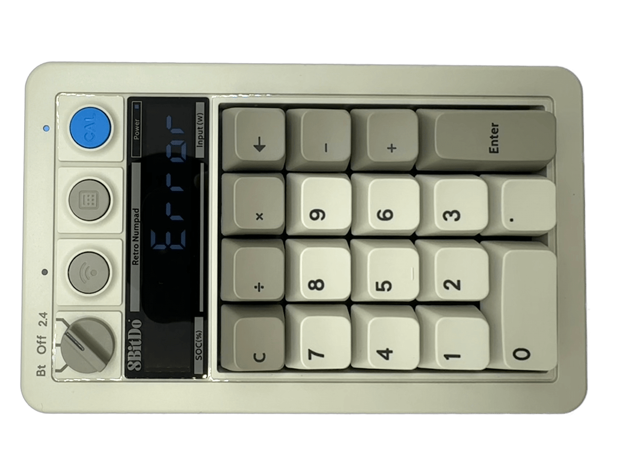
However, this calculator is capable of displaying Error message on overflow or illegal operations. Moreover, the button to toggle modes is a momentary one, and it’s used to enable or disable Num Lock (when combined with C button). Momentary On or OFF messages work only on Windows (I guess they are linked to Num Lock LED signals from the host). This suggests that it’s not just a random cheap calculator chip.
Additionally, the device can display battery percentage and the manual claims it also shows “input power” in watts. I don’t have the latter feature, plus the diagram in the manual suggests the device takes 368W to charge. They likely meant milliwatts.
Accidentally, I also discovered that holding CAL and 1/2/3/4 enables hidden games - PLAY-G1, PLAY-G2, PLAY-G3 and PLAY-G4. They are similar in design to those from Videomaster Enterprise (as seen on Ashens video).
Knowing that, I was certain that what I envisioned was doable - at least for the manufacturer.
Downloading firmware #
As a starting point, I went to look at official software used to configure devices and update firmware. Although the software is available on macOS, it doesn’t support the Retro Numpad there. I had to use a Windows machine. Firmware can be flashed to any available version (including downgrades), and the Retro Numpad has two firmware versions listed, so I was able to observe the update process directly.
Next, I needed to get firmware files. I discovered that some older devices were covered by FWUPD and were uploaded into LVFS. The process to update them is described at github.com/fwupd/8bitdo-firmware and blog post at ladis.cloud. I needed to figure out “type” of my device, and I tried to do so without sniffing traffic from the app. It turned out that simply requesting type 0 gives all the results. From there I know that the USB adapter for 2.4GHz mode is 74 and Retro Numpad itself is 73.
curl -X POST -H 'Type: 73' -H 'Beta: 1' \
  http://dl.8bitdo.com:8080/firmware/select
{
  "msgState": 1,
  "error": "",
  "list": [
    {
      "date": "2024-06-11",
      "fileName": "Retro Numpad",
      "androidDownload": 0,
      "iOSDownload": 0,
      "readme": "1. 修复充电显示信息错误的问题。\r\n2. 优化电池电量检测的准确性。",
      "type": 73,
      "version": 1.059999942779541,
      "winDownload": 6567,
      "fileSize": 115228,
      "filePathName": "/firmwareFile/upload/07fefb27-1314-4df0-abe8-059e0fb9935b.dat",
      "macDownload": 0,
      "exists": false,
      "fileURL": "/var/lib/tomcat9/webapps/firmwareFile/upload/07fefb27-1314-4df0-abe8-059e0fb9935b.dat",
      "readme_en": "1. Fixed the issue of incorrect charging display information.\r\n2. Optimized the accuracy of battery level detection.",
      "id": 1906,
      "beta": "",
      "md5": "923698894ED467828DA8395F46DA1B67"
    },
    {
      "date": "2024-04-24",
      "fileName": "Retro Numpad",
      "androidDownload": 0,
      "iOSDownload": 0,
      "readme": "1. 出厂固件。",
      "type": 73,
      "version": 1.0499999523162842,
      "winDownload": 2,
      "fileSize": 115228,
      "filePathName": "/firmwareFile/upload/075ce0c1-142d-4253-a533-d888e9f10218.dat",
      "macDownload": 0,
      "exists": false,
      "fileURL": "/var/lib/tomcat9/webapps/firmwareFile/upload/075ce0c1-142d-4253-a533-d888e9f10218.dat",
      "readme_en": "1. Factory firmware.",
      "id": 1884,
      "beta": "",
      "md5": "923698894ED467828DA8395F46DA1B67"
    }
  ]
}
To download firmware, you just need to download path from field filePathName from the same server that hosts API - http://dl.8bitdo.com:8080/.
The first thing to do after obtaining firmware files was to analyse it with binwalk and check entropy. Nothing was extracted, and entropy suggested encryption. Most people with not enough spare time would stop here, but I wanted to know more. Maybe files are decrypted by a flasher app, maybe encryption is weak or keys have leaked.
If you were to analyse different firmware flashing application with unknown source of files, you could always start with intercepting network traffic using Wireshark and mitmproxy (on macOS, I recommend Proxyman). To investigate system calls (e.g. to see what application is writing to a disk) you can start with procmon.exe from SysInternals on Windows (strace on Linux, I have no experience on macOS).
Sniffing USB #
I wanted to know how the app performs flashing operation. I didn’t want to perform static analysis, as the application is nearly 200 MB (with the main executable being 170 MB) as it supports all the various 8BitDo products; even after a brief look in Ghidra it looked like a nightmare. Because, at this stage, I only needed to confirm whether the file was sent to the device as-is, and you can flash the device multiple times, I opted for capturing USB traffic generated by the actual flashing process.
Discovering protocol #
To sniff USB traffic, I used USBPcap and Wireshark on a dedicated x86 Windows PC. It should automatically be available in Wireshark as a capture device, and it’s worth using the GUI to manually discover and filter out USB devices. Otherwise, capture will be overloaded with everything that’s connected via USB, including Wi-Fi cards. Moreover, bus IDs are not corresponding to what you may find in Windows Device Manager. What’s important for this project and many similar ones that include flashing firmware is to keep Capture from newly connected devices enabled, as many devices reset the entire USB stack after firmware is flashed and get new ID.
My first round of investigation involved connecting numpad, checking what Windows thinks about it, starting capture and then launching the official app and proceeding to the firmware update section. That way, I could see initial communication and confirm it’s using HID for both normal operation as a keyboard and internal communication with MCU. I only focus on numpad itself, not the wireless adapter as it’s not interesting to me in terms of device hackability (but it can also receive firmware updates).

HID is a powerful protocol, which is part of the USB standard. For our use case, the most important aspect is that it doesn’t require extra drivers (apart from HID, which is part of the OS or a common library) and communication with the device can be done from user land without any issues. While commonly associated with keyboard and mice, it’s very versatile. For example, Elgato StreamDeck uses HID to send key presses and receive images for individual displays (I investigated it quite a bit when dealing with USB stack Raspberry Pi 3B+ not handling python-elgato-streamdeck library for use with my RPiDeck project).
When working with USBPcap in Wireshark, it’s also worth keeping Inject already connected devices descriptors into capture data to confirm that we’re targeting the correct device and what is their ID (here it’s 1.27.x as 0 is only root device). Normally, only the OS queries USB device for descriptors upon connection to display details in device manager or show notification about new device and check whether drivers are required. When using the mentioned feature, relevant reconstructed packets will show immediately after capture start.

After launching the 8BitDo app, we can immediately see that firmware-related communication is present on two sub-devices - 4 and 5, while the keyboard part is working on sub-device 1. For the keyboard, I pressed 0 on numpad, which uses scan code 0x62, and we can see that there’s key-down interrupt (HID Data), ack from the host (computer), key-up even and again ack from the host. For firmware related communication, we’ll need to see more details to proceed.

Reviewing update process #
After clicking Update it takes around 20 seconds for it to finish and the same can be seen in USB traffic. It seems like sub-device 4 is for reading and 5 for writing data. The majority of transfer in terms of data suggests that flash is updated in chunks up to 64 bytes long and first data is read from flash and if it differs, then new data is sent by the app to be written. That way, the process is way quicker and saves a lot of flash write cycles. After further analysis, something may be deduced about data encryption.

Finally, some checks are performed and the device resets with the new device reconnecting to the host as 1.28.x

If we filter the entire communication to what the host sends as USB interrupt data out with 64 bytes as payload, we get 2259 packets. Right away, it’s clear that USB HID data contains some form of command and data. Most of the time it’s writing data, from time to time, there’s a sequence with 3 packets, likely indicating the end of a page, new page address and start of the next page.

The end of session looks similar, but the rest of memory is not written, hence the wall of (what I suspect) memory block IDs.

Reverse engineering data sent to device #
Dumping all writes in hex into a text file further confirms previous theories. I attach conversion of different captured session with Wireshark filter usb.src=="host" && usb.data_len=64 as write_analysis.csv.
Each packet from the host has the following structure (field names from CSV file are in bold):
- 2b prefix - fixed prefix
0x8105; I don’t have other devices that show up in the 8BitDo app, but it doesn’t seem to correspond with device model or serial number - 1b cmd - command
- 3b param - unknown parameter, always
0x000000except for first and last packets (CMD0x00where it’s0x210100) - 1b data_len - number of bytes from data field to be used (up to 46); if less than 46, then data is padded with zeros
- 1b padding - always
0x00 - 10b address - data write address, big-endian
- 46b data
Commands are the following:
0x00(2/2260 packets) - session start/end- all fields except param are 0
- weird first parameter is
0x210100 - data length is 0
0x03(2172/2260 packets) - data write- address field contains flash address advancing weirdly, but matching 46-byte write pattern
- data length is 46
- data contains bytes written to flash
0x04(25/2260 packets) - data block write start- address field contains offset
- data length is 0
- after this packet, data write packets start, always 90 (=4140 bytes) except last write (here 12)
0x07(1/2260 packets) - update finish- final command before session end (CMD
0x00) - data length is set to 8
- address is
0x00000800000000000000 - data is
0x0000000000000000
- final command before session end (CMD
0xc1(1/2260 packets) - write start- first command after session start (CMD
0x00) - data length is 0
- address and data* are 0 (as expected)
- first command after session start (CMD
0xc3(58/2260 packets) - set data block address- sets flash address to start writes (if so, followed by CMD
0x04and series of CMD0x03) or just to touch (no writes needed) - seen at the end of session - data length is 12
- actual data structure:
- 2 bytes for block address, increments by
0x0010 - 2 bytes for block size, always
0x0010 - 2 bytes for
0x0000 - 4 bytes for fixed
0xCCCCCCCC
- 2 bytes for block address, increments by
- sets flash address to start writes (if so, followed by CMD
0xc4(1/2260 packets) - write finish- final command before write finish (CMD
0x07) - data length is 8
- address is
0xbf8a0800000000000000, may have some meaning - data is
0x00c2010069000000, may have some meaning
- final command before write finish (CMD
Conclusions on data written over USB #
After analysis of the source firmware file and data writes, it seems like the majority of the file is uploaded and only around 1% of 46-byte pages are omitted. They are distributed rather evenly across the source file; slightly foreshadowing my investigation, I can say that it matches the 4 KB structure of flash memory onboard the device.
This means that the flasher app applies the file downloaded from the vendor as-is, without any decryption and thus the firmware stays encrypted even on the device.
To fully reverse engineer the whole flashing process, we’d need to analyse messages sent from the device to the host in the same fashion. I believe that those would only be message acknowledgments and flash reads. If anyone is interested, USBPcap captured during update from 1.05 to 1.06 (07fefb27-1314-4df0-abe8-059e0fb9935b.dat) is uploaded here as fw106.pcapng.
Looking at other 8BitDo firmware #
I repeated USB-based analysis for both versions of firmware available for the numpad, and it looked the same. I was still intrigued to find whether other 8BitDo devices are hackable - to analyse them in context of those devices (to give answers to the 8BitDo community) and my numpad (maybe encryption key leaked? in such a case, I don’t believe a firmware update could be applied to change it live).
I created a simple Python script to fetch all firmwares described in AP from the beginning and do a simple analysis. I decided to create a directory structure $deviceType/$firmwareId to help with splitting download and analysis stage. Each subdirectory of firmware contains an excerpt from source JSON and the firmware file itself (stored as firmware.dat to avoid issues with weird names).
On each firmware, I run binwalk with the following flags:
--search-allto search for all signatures--matryoshkato work recursively if any firmware file contains further containers--logto store analysis results as JSON for later analysis
As a side note - when I initially tried to extract all files found at the same time, I faced the issue with JSON produced from version 3.1.0, which is not present in binwalk compiled from the latest master branch. I raised a relevant issue, which, I hope, should be released soon (working code is already there, they just need to release a new version), but in the meantime I switched from blind extraction and randomly parsing invalid JSON into just looking at valid JSON.
Initially, when I did that analysis with a set of bash scripts and later with Python (but incorrectly parsing invalid JSON), I noticed that some files were being extracted. Having hopes, I needlessly proceeded to generate reports as I suspected that some devices might have firmware without encryption or that encryption was introduced in later firmware. However, I should have fixed the invalid JSON issue earlier, as all false-positives look like this:
[
{
  "Analysis": {
    "file_path": ".../firmware_analysis/raw_data/43/1777/firmware.dat",
    "file_map": [
      {
        "offset": 42042,
        "id": "83250c72-a340-4b67-9725-56c407c64021",
        "size": 56,
        "name": "zlib",
        "confidence": 250,
        "description": "Zlib compressed file, total size: 56 bytes",
        "always_display": false,
        "extraction_declined": false
      }
    ],
    "extractions": {}
  }
}
]
Seeing that, I introduced a simple check that looked at the size of each file identified inside the firmware. If it was less than 1 KB, then it didn’t count into marking the entire firmware as “binwalk-able”. That way, every firmware was identified as encrypted and sophisticated report was no longer needed. Unfortunately, I couldn’t find an easy way to calculate entropy for files in Python, but I assume that if binwalk can’t find any pattern, then those are most likely encrypted.
Analysing hardware #
Teardown #
The next logical step for me was to just disassemble my numpad and at least identify the microcontroller, ideally find some debug ports.
In order to do so, only 4 screws need to be unscrewed. They are under rubber feet. After disconnecting the USB board and battery we can see all the interesting parts.

On this side of the board, there are hot-swappable mechanical switches, a buzzer (used in purely in built-in hidden games), connectors for battery and charging chip, USB board connector (J23), unpopulated debug port (J22), 7-segment display controller (TM1640) and the MCU - Telink TSLR8271. Full chip markings: TLSR8271 / F512E746 / ZYL2404 / EML383.
MCU #
Telink TLSR8271 is a SoC with built-in Bluetooth Low Energy, 2.4GHz radio for protocols like Zigbee, USB support and enough GPIO to handle all keys + display. It has a custom RISC-based MCU, 64 KB SRAM and 512 KB flash. Full documentation is at Telink website. Overall, this is a competent chip for the job.
Firmware files take 113 KB, so there’s plenty of free space. Unfortunately for this story, the chip also has hardware support for AES-128 with AES-CCM mode for code authentication. I couldn’t find any details regarding firmware encryption, apart from a changelog entry for version 0.8.0 of documentation stating:
Section 1.2.5 Flash Features: Removed firmware encryption related feature description
It’s the same for all other chips from the TSLR827x family. Details are probably hidden behind NDA, and it’d be an example of security by obscurity, likely triggered by a series of vulnerabilities called SweynTooth or attacks on older Telink chips related to hacking low-cost Xiaomi thermometers.
From there, there are three options:
- breaking AES-128 (if that’s the case, then we’re screwed)
- somehow obtaining key pair - unless 8BitDo does something stupid, this is extremely unlikely (given their excellent security practices I could discover, they likely have one key per product anyway)
- forcing the MCU to decrypt flash and send it to us (e.g. by running malicious firmware that doesn’t overwrite the program) and later flashing decrypted firmware (if that’s allowed by the chip)
Only the third one is somehow viable (especially with old examples of hijacking firmware update process), but it’s definitely outside the scope of this research. I couldn’t find any research in this field.
Other components #
It’s worth mentioning that the firmware update process does not use native Telink flasher, even though this chip supports flashing over USB. I verified that using Telink Burning and Debugging Tool (BDT) (important thing here - in BDT, our chip falls under 8267 family) and by analysing USB traffic during flashing. For direct communication with the chip, it’s likely that an unpopulated 10-pin J22 connector is used in conjunction with Telink EVK or some other interface. This is also supported by the presence of capacitors and exposed test points on traces leading to the connector.
No other component is interesting - everything except driving the 7-segment LED display is done in one SoC
Conclusions on hardware #
Unfortunately, this means that in this project, attacking the firmware flashing process is a dead-end.
But it’s a good place to compliment the hardware design of the product - there’s good access to the PCB for changing switches, the battery pouch is not exposed, both battery and USB connector board use internal connectors (i.e. they are not hard-wired). Microcontroller is also a good fit for a job.
Conclusions #
Lack of hackability is not necessarily a bad thing in this case. Since anyone having access to a computer with a USB device attached could flash any firmware, it’s scary to think about a programmable keyboard having keyboard-level access to a computer. Maybe it’d be better to have a special flashing mode enabled physically on the device, but I also understand manufacturers wanting to keep their intellectual property safe (this is more important on their other products, most notably retro gaming accessories).
While nothing was achieved with regard to the original goal (besides an email to 8BitDo), time was definitely not lost. Firstly, I now have an answer to my question “can you modify feature of 8BitDo product” with enough evidence to just drop the idea unless Telink SoC is found vulnerable or some leak happens. As for the journey - it was the first project I reverse engineered at least part of USB HID-based protocol on my own, contributed to binwalk project and spent some more time with Python. I did hope to try some new approaches to extract & analyse scenarios, but I solidified my experience with the current style of work.
And for the final reference, I discovered the Canon LS-100TKM by watching LGR’s This Weird Mouse Calculator Numpad USB Thing from 2008.