Flipper Zero interface board - part 1

Today I used prototype boards I purchased with my Flipper Zero pre-order for the first time. I think I didn’t use them before (and I have Flipper for over 6 months) because the single purpose for them that was repeated over and over again was to expand a device with Wi-Fi or general-purpose 2.4GHz radio, which never appealed to me. However, recently, I found a category of FlipperOS applications that’s quite obvious - I2C interfaces, for example for light or temperature sensors. This quickly rendered my previous attempts at creating such a self-contained portable I2C client from scratch obsolete and demanded the soldering iron to be turned on.
It’s part 1 of quick blog posts on the topic of Flipper Zero interface board I’m making. There’s a chance that the final part will be a longer entry published alongside source code and hardware schematics. For now, the plan is to revive the idea of more frequent posts that show smaller iterations of my projects. Classic long pieces are not going away.
Previous attempts I mentioned in the intro include esp8266-portable-light-sensor I made a month ago - ESP8266-based portable light sensor with serial port output and OLED display. It was a quick re-use of development instance of sensor header from my other project esp32-window-light-sensor, which is ESP32 based Window Light Sensor with HomeKit and MQTT support.
I needed to measure brightness of a night light to validate battery consumption in a controlled environment (i.e. dark, for example closed box). Therefore, the long, but flat cable used in window light sensor was ideal to have some display outside, so it’s not affecting the measurement. While a flat USB cable connected to some external I2C card would solve the issue as well, I was thinking about several other applications that required a more portable or self-contained solution (e.g. for long-term logging). The sensor header is using I2C sensors soldered directly to KANDA IDC-10 connector intended to be soldered to the board. I really enjoy this style of connectors as they are more practical than typical breadboard “goldpin” cables, especially when there’s a chance you’d want to use longer cable or the layout is fixed, yet reconnections are required. The mentioned attempt was crude, but worked well.

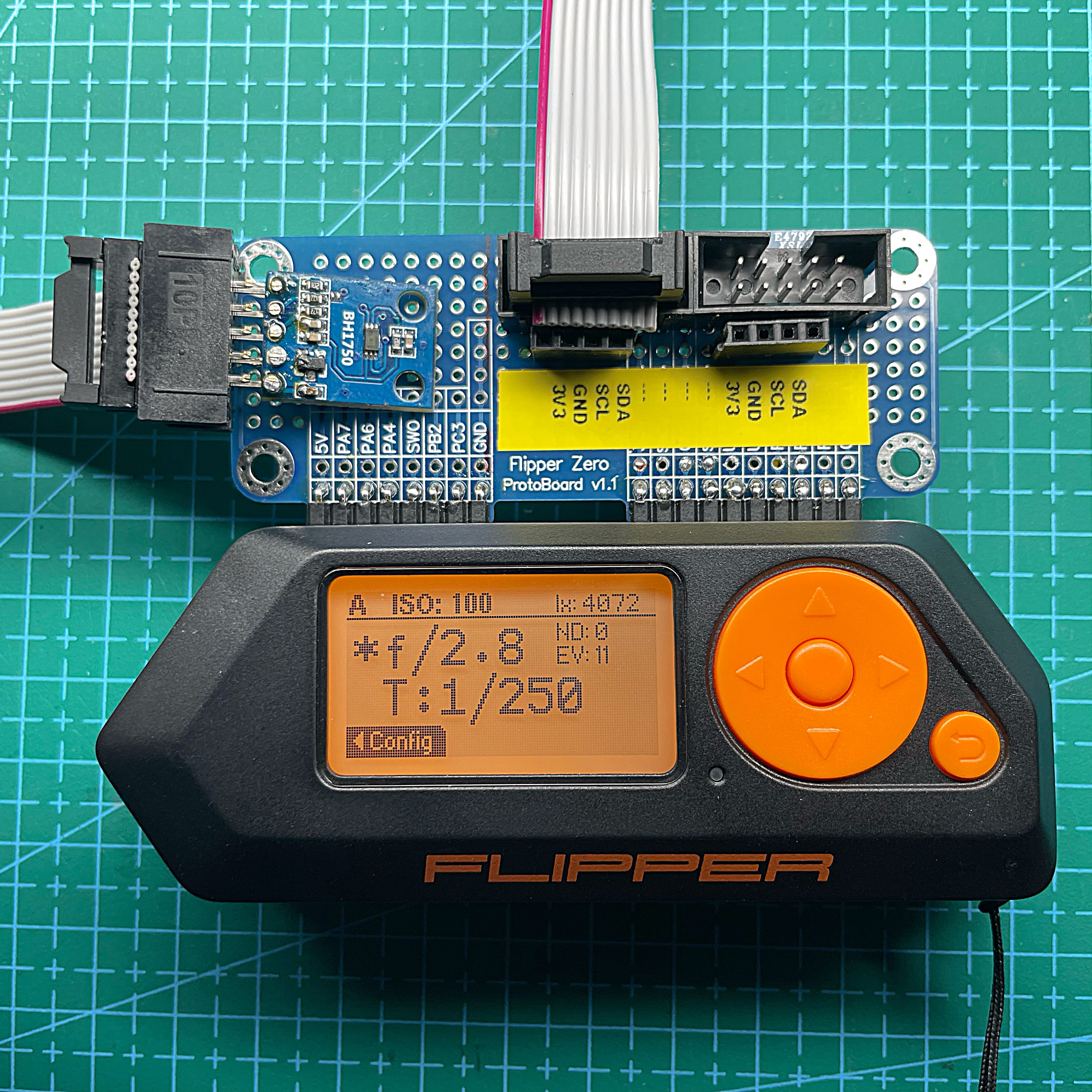
10-pin variant of KANDA was used since it allowed me to solder BH1750 in a GY-302 kit that has 5 pins directly to the socket without any interface board. I also attached another I2C sensor there to use free pins. Moreover, I couldn’t find any other variant locally in reasonable price.
Keeping my affection towards KANDA connector and having “standardized” I2C over IDC-10 pinout (2-4-6-8-10 as: module dependent pin (e.g. address select), SDA, SCL, GND, 3V3; 1-3-5-7-9 optionally bridged to “+1"s) I decided to incorporate it on my Flipper Zero interface board as well. To be exact - twice, to make it extensible. For ease of use, two 4-pin sockets (“goldpin” style) were added, so there’s an option to connect sensors with pins directly to board, instead of relying on an IDC cable that has sockets on both ends (IDC board connector has pins).
The board followed a quick and dirty approach using Kynar wire (AWG 30 with insulation removable by soldering iron during soldering). However, to provide some enforcement for angled goldpin connectors used to attach board to Flipper Zero, I used solder generously from both sides. Proper implementation (that’s quite far from prototype stage I’m on right now) demand proper PCB, more robust connector and some grip handles.
The final touch for the I2C part of the board was a printed label marking pinout of soldered sockets. SPI will be implemented next to it when my external CC1101 radio with detachable antenna arrives. Flipper Zero has all the SPI pins on one half of the interface, and all I2C ones on the other, making my interface board cleaner and easier to implement :)
Few photos of this iteration below - board itself and attached to Flipper Zero with BH1750 from aforementioned repurposed esp8266-portable-light-sensor connected.


I2C can be easily consumed using one of apps preinstalled in
unleashed firmware - for example
BH1750 Lightmeter app or
i2c Tools app.

